After putting together my previous post, I found out about a useful Scrap Mechanic logic technique that I’d like to go over today.
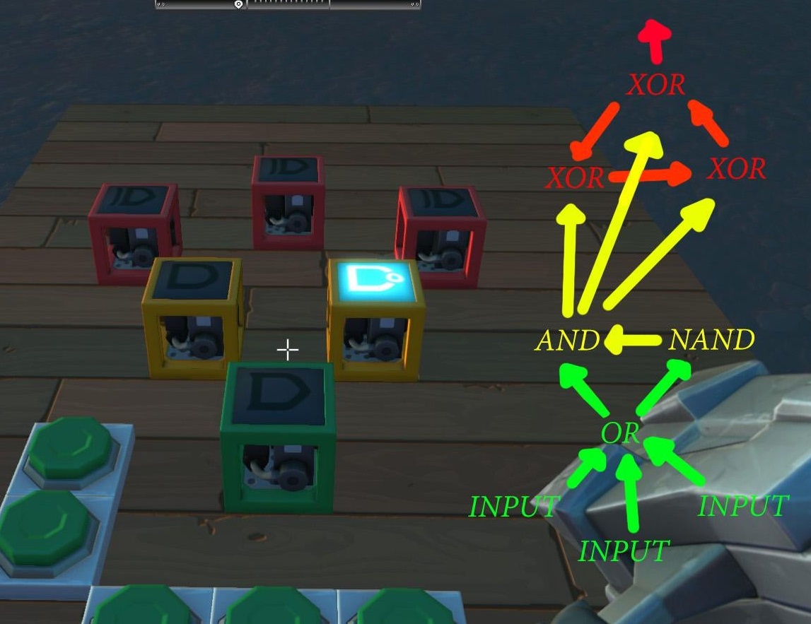
This is a design by Aeon_phoenix on Reddit for a T flip-flop. It turns out T flip-flops are really popular with in-game crafters across Scrap Mechanic, Minecraft, and some other games. Pressing any one of the input buttons will cause the output to toggle on or off, so it’s a great way to activate doors, lights, killsaws, etc. With this, you can use the same button to open/close a door from either side. You can take an output signal off any of the XOR gates.
<BLAH BLAH BLAH>
Normally I’d never have given them any thought, since the only designs I knew about for T flip-flops involved clocks and a (relative) ton of gates. Back in school, we mostly used programmable logic chips that could hold tons and tons of gates and be internally rewired in seconds, but in Scrap Mechanic you have to swim around like a jerk looking for giant clams to get glue that you can use to build the gates. It works out to be about 1-2 minutes of boring grinding for every gate, so the fewer your design takes, the better.
</BLAH BLAH BLAH>
How it works
Single Tick Pulse Generator
The NAND gate in yellow is just an inverter (a NOR gate would work as well). A 0 at the input produces a 1 at the output, and a 1 at the input produces a 0 at the output. By sending the same activation signal to both the yellow AND and the NAND gates at the same time, you ensure that you’ll pulse the output of the AND gate for exactly one tick. After one tick, the 1 from the button press at the NAND gate’s input makes it through the NAND gate, and it produces a 0. That causes the AND gate to stop sending your button press through to the XOR gates. So no matter how long or short a time you hold down one of the input buttons, you’ll only get a single tick of 1 sent through to the XOR gates. (So if you ever have a design where you need to convert a button press into a single-tick pulse, you can duplicate just the bottom half of the circuit.)
| Input 1 | Input 2 | XOR Output |
|---|---|---|
| 0 | 0 | 0 |
| 0 | 1 | 1 |
| 1 | 0 | 1 |
| 1 | 1 | 0 |
XOR Latch
You can think of an XOR gate as a switch-controlled inverter. If Input 1 is off, then it passes Input 2 through unmodified. If Input 1 is on, then Input 2 gets inverted. That’s what’s happening above, the output signal across the XOR gates stays the same when their second input (the AND gate) is 0, and gets toggled once when the second input is 1.