All right, you’ve probably seen some of the awesome Scrap Mechanic videos out there like this:
Chances are good that if you tried to replicate this thing, it blew up in your face and you have no idea why.
The official wiki and the in-game handbook are a little light on details (as of this posting anyway) of what you can do with the logic gates in Scrap Mechanic. I’m not going to try and make you into an electrical engineer today, my goal here is just to give you a quick overview of digital logic so you’ll be able to replicate designs like the one above.
Logic Gate Basics
Each gate has a single output value, and any number of input values (or at least, they seem to be able to take 0-3 inputs pretty well).
You can represent the output you’ll get from a given set of inputs using a “Truth Table”, like so:
| A | B | A OR B | A NOR B | A AND B |
| 0 | 0 | 0 | 1 | 0 |
| 0 | 1 | 1 | 0 | 0 |
| 1 | 0 | 1 | 0 | 1 |
| 1 | 1 | 1 | 0 | 1 |
You can find all the truth tables online, I won’t bore you with them here. Just look for “digital logic truth tables”
In Scrap Mechanic in particular, our building blocks are going to be AND, OR, XOR, NAND, NOR, NXOR, and a “Timer” gate that mirrors its output with a programmable delay.
OR gates
As the handbook describes in-game, you can use an OR gate to combine two signals for a single purpose. I also use them often as wiring. On a real logic gate IRL, you can easily wire the output of something back to its own input if you want. In-game, though, you can only have one connection between each pair of gates, and it’ll only go from one output to one input. I’ll come back to this later in the article.
AND gates
are a good way to turn a signal off. If you combine a signal “X” with a logical “0” (say, from a switch that’s off), the output will be “0”. If you combine X with a “1” (like from a switch that’s on), the output will be the same as “X”, so it’s like you’re using the switch to force X off.

NOR gates
I often use NOR gates to invert a signal (change 1 to 0, or 0 to 1). IRL there’s a “NOT” gate that does this, but if you check the truth table above, you’ll note that NOR-ing a given input together with a 0 will always give you the inverse of the input signal.
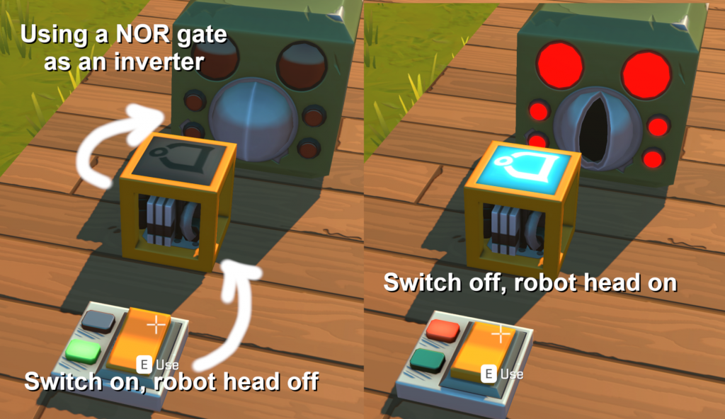
Advanced Building Blocks
Oscillator
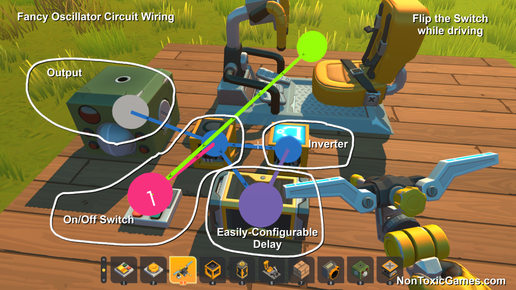
You can wire up an inverter (NOR gate) back to itself through a delay in order to make a circuit that will continuously pulse a signal. This is a quick and easy circuit that’ll let you avoid having to manually pound the button attached to your vacuum pump to unload vegetables at a Packing Station.
I like to jazz things up with a couple of minor adjustments: Replace one of the dummy gates with a Timer so you can configure how quickly the circuit repeats. Replace the other dummy gate with an AND gate and attach a switch to allow you to switch the oscillator on and off. Then you can get extra fancy and attach the switch directly to your Driver’s Seat, and you can turn the oscillator on and off by just hitting a number key while you drive!

Flip-Flop
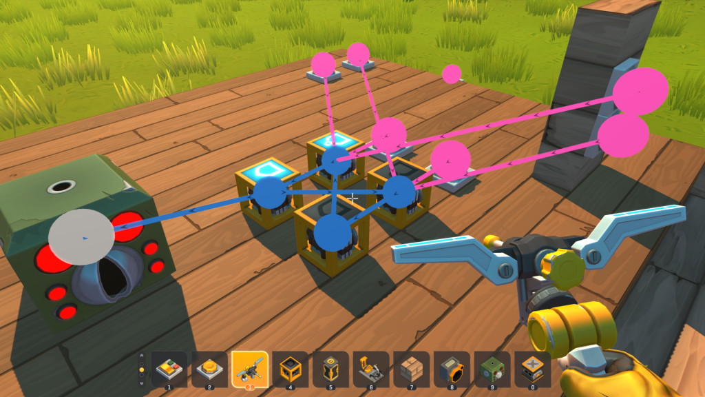
Probably the most important circuit to learn about is a basic memory circuit known as a “Flip-Flop” or “SR Latch“. Even if you don’t want to dig into how it works under the hood, it’s pretty straightforward to put one together and use it. It’s basically just two NOR gates tied together as outputs from and inputs to each other. It will remember the output, and only change it when you give it an input.
A picture is definitely worth a thousand words in this case, so here you go:
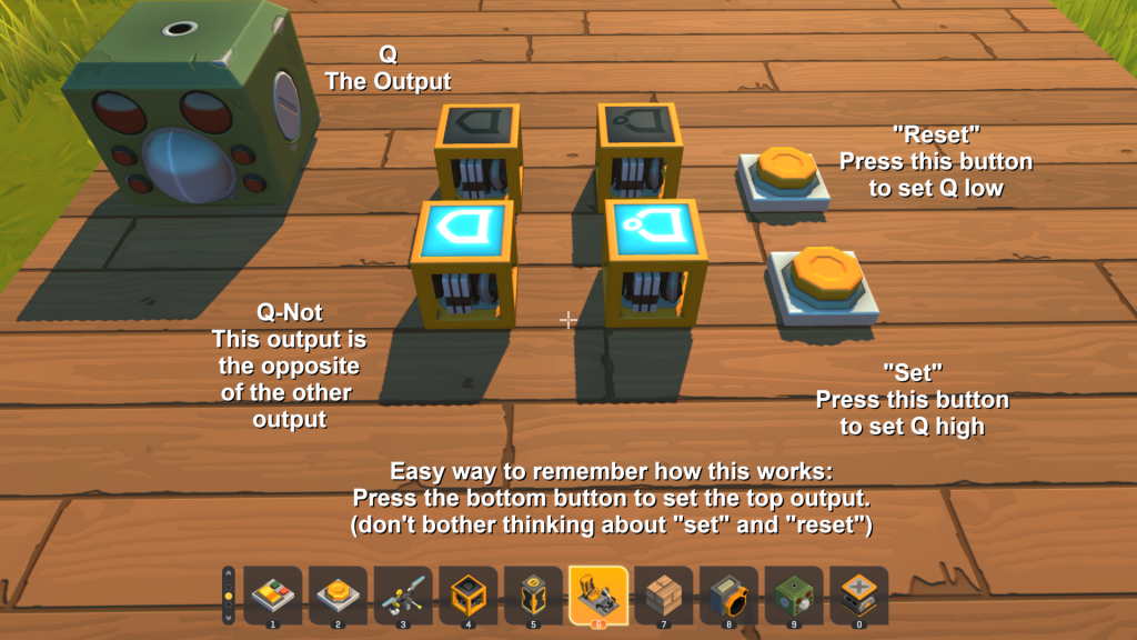
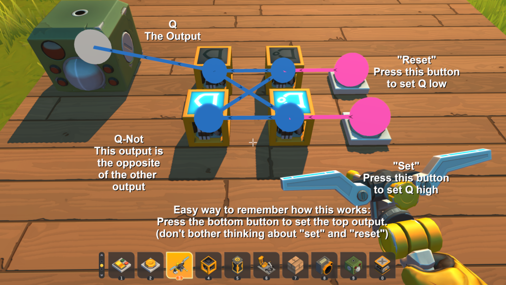
Wire the top NOR to the top OR, then the top OR down to the bottom NOR. Wire the bottom NOR to the bottom OR, then wire the bottom OR back into the top NOR.
UPDATE: It turns out there’s an easy way to keep this flip-flop design from going crazy when you spawn it in or briefly tap an input. Just put an extra connection from one of the NOR gates to the other.
Your input buttons (or other signals) go into the NORs. Your outputs come out of the ORs. You can dig into the details of how this stuff works on Wikipedia or elsewhere, but the important thing to know is this: As shown above, you press the TOP button to turn OFF the top output, and you press the BOTTOM button to turn ON the top output.
BAM!! You can wire multiple buttons to the same input, so this is a great way to build a door you can open and close from either side, or an elevator you can call from either the top or the bottom.
Caution(You can dive down the rabbit hole about why this happens by looking into “SR latch setup and hold time”, or meticulously drawing out a tick-for-tick diagram of the signals)
I should mention here that you can do this with just 3 gates in Scrap Mechanic, by wiring one of the NOR gates directly to the other. The downside to that approach is that it’ll turn into a crazy oscillator when you spawn the circuit in. With the circuit shown above, a super quick feather-tap on one of the buttons can put it into a crazy oscillating state too.. There’s a way to work around this by adding more gates, but those logic gates are a lot of work to farm, so I think you’re better off just being careful to hold the button down for a split second.
EDIT: Thanks to a suggestion from SlickSwagger on Reddit, it turns out you can fix this by just adding an extra connection from one of the NOR gates to the other one! This causes the signal going from one of the NOR gates to the other to be held high for an extra tick, so transient oscillations will get damped out pretty quickly. You can still get some oscillations if you tap one of the inputs just right, but they disappear within half a second. If this thing absolutely has to be robust against any kind of button press, you can harden it by wiring the input signal to a trio of OR gates that are then connected to each other and to the circuit’s input. This enforces a longer hold time.
Pulse Generator
There’s a really quick and easy circuit you can make by just adding one more thing to the flip-flop. If you wire a button to the top input, then wire it through a Timer (with a delay!) to the bottom input, you have a circuit that will set the bottom output for a fixed period of time, then turn it off. This is a great way to turn on the kill-saws at the bottom of your car for a few seconds, then turn them back off to save on gas after they’ve ripped your enemies to shreds. See it in action below on YouTube.
More Reading
You can read more about digital logic at this SparkFun site (no affiliation with me), or pretty much anywhere online. Just punch “Digital Logic” or any of the other terms from this article into DuckDuckGo and you should be good to go.
